Translate

Difference between Force method and Displacement method of analysis of structure

  •  For an indeterminate structure,  the condition of static equilibrium equations are not sufficient to analyze the structure.  To analyze an indeterminate structure,  some additional equilibrium or compatibility equations are required. 
  • In force method of analysis of indeterminate structure,  the unknowns are taken as forces (i.e, member forces or reaction). While in case of displacement method of analysis of indeterminate structure, the unknowns are taken as displacement (i.e, Δ or ө).
  • In force method of analysis of indeterminate structure,  first force displacement equations are written and then unknown forces are calculated from compatibility criteria. While in case of displacement method of analysis of indeterminate structure, first force displacement equations are written and then unknown displacement are calculated from equilibrium equations at joints. 
  • Force method of analysis of indeterminate structure is suitable when degree of redundancy is less, i.e, degree of static Indeterminacy is less than degree of kinematic Indeterminacy.  While displacement method of analysis of indeterminate structure is suitable when degree of freedom is less, i.e, degree of kinematic Indeterminacy is less than degree of static Indeterminacy. 

Difference between Force method and Displacement method of analysis


How to calculate Kinematic Indeterminacy of a structure

  • Kinematic Indeterminacy is defined as the total number of joint displacement present in any structure. 
  • Kinematic Indeterminacy is also known as unknown degree of freedom. 
  • Degree of kinematic Indeterminacy is used in case of displacement method of analysis of structure. 
  • Degree of kinematic Indeterminacy is calculated as the difference between the total possible degree of freedom and known degree of freedom. 
  • Now,  as support reactions are generated due to restraint of deformation provided by the support.  So,  the number of available support reactions will be equal to the number of restraint joint displacement. 
Dk = (total possible degree of freedom) - (Number of available support reaction) 


Kinematic Indeterminacy, Dk

  • Now, in case of internal hinge
    • Each internal hinge will add 4 degree of freedom in plane frame case and 9 degree of freedom in case of space frame
    • Each joint hinge will add (m'-1) degree of freedom in plane frame case and [3(m'-1)] degree of freedom in case of space frame. Here m' is the the number of members meeting at the hinge joint.
  • In case of inextensibility of members, the extension of members are restricted. In this case m number of degree of freedom will be subtracted from the degree of kinematic indeterminacy.


How to calculate Static Indeterminacy of a structure

  • A statically determinate structure is such structure for which conditions of static equilibrium equations are sufficient to analyze the structure.  While for the indeterminate structures,  static equilibrium equations are not sufficient to analyze the structure.
  • This means that in indeterminate structure,  the number of unknown forces in members or the support reactions are in excess of number of static equilibrium equation available. 
  • So,  the static Indeterminacy can be defined as the difference between total number of unknown forces and total number of equilibrium equation available. 
Ds = (total unknown) - (available equation) 

Static Indeterminacy for beams

  • The basic rule to calculate the static Indeterminacy for any structures is to find the difference between total number of unknown and total number of equilibrium equation available. 
  • To,  determine static Indeterminacy for beams,  the simple procedure is that one should try to make given beam as a cantilever beam by adding constraints and removing all other support reactions. 
Ds= ( support removed - constraint added) 
  • Note:-  Internal Indeterminacy of a beam is always zero, i.e, beam is always internally determinate and for beam, total Indeterminacy is always equal to external Indeterminacy. 

Static Indeterminacy for truss

  • The basic rule to calculate the static Indeterminacy for any structures is to find the difference between total number of unknown and total number of equilibrium equation available.
  • In truss, member only carries axial force and no other internal reactions. So,  each member of a truss will give one unknown.  And the reactions developed at support will also constitute for the total number of unknown. 
  • Now, at each of the joint present in the structure, the force equilibrium equation will be available.  So,  the number of equations will be ( 2 each for plane truss)  and ( 3 each for space truss). 
    • Ds = (m+r) - 2j 👉  plane truss 
    • Ds = (m+r) -3j 👉   space truss 
      • where m = number of member
      • n = number of reactions
      • j = number of joints
  •  Note:- External Indeterminac
    •  (r-3) for plane truss
    • (r-6) for space truss

  • Internal Indeterminacy  
    • [m - (2j-3)] for plane truss
    • [m - (3j-6)] for space truss

 Static indeterminacy for Rigid Frame

  •  The basic rule to calculate the static Indeterminacy for any structures is to find the difference between total number of unknown and total number of equilibrium equation available.
  • In rigid plane frame,  each member carries 3 forces and in case of space frame,  each member carries 6 forces. And the reactions developed also constitute for the unknowns.
  • Now,  at each of the joint present in the structure,  the equilibrium equation will be available. So,  the number of equations will be (3 each for plane frame)  and ( 6 each for space frame). 
  • Now, for m' member meeting at a hinge location, there will be extra {(m'-1) independent equation for plane frame} and {3(m'-1) independent equation for space frame}.
    • Ds = 3m + r - 3j - Σ(m'-1)   👉 plane frame
    • Ds = 6m + r - 6j - Σ3(m'-1) 👉 space frame
      •  where, m = number of member
      • r  = number of reaction
      • j = number of joints
      • m' = number of members meeting at a hinge 


Difference Between Shallow and Deep Foundation

  • Foundations are defined as a substructure element which is used to transfer the heavy superstructure loads to the soil in such a way that neither the surrounding soil is stressed in excess of allowable stress of soil nor it undergoes deflection more than permissible deflection.
  • Foundations are broadly classified of two types:-
    • Shallow Foundation 
    • Deep Foundation

Difference between Shallow and Deep Foundation

  • For a Shallow foundation, the depth of foundation is equal to or less than its width. Whereas for Deep foundation, the depth of footing is equal to or greater than its depth.
  • A shallow foundation is located at very low depth, whereas a deep foundation is constructed at more depth.
  • In case of Shallow foundation, loads are primarily supported by the action of end bearing. Whereas for Deep foundation, loads are supported partly by frictional resistance around the surface and partly by bearing at the base of foundation.
  • The construction of shallow foundation is done in open excavation. Whereas the construction of deep foundation is generally carried by boring or drilling well beneath the ground. This will lead to a better visual inspection in case of a shallow foundation over deep foundation.
  • Shallow foundation are in general cheaper than deep foundation in construction. Deep foundation requires more machinery and more technicality which increases the costs.
  • Allowable load in case of shallow foundation is way less in comparison of deep foundation. So, for heavy superstructure construction, Deep foundation is always preferred over shallow foundation.
  • Lateral effect of soil is better resisted by the deep foundation in comparison to that of shallow foundation.
  • Shallow foundation requires less labour in comparison to that of deep foundation. Deep foundation even requires skilled labour.
  • Shallow foundation is not suitable for soils which are weak in upper stratum. In this scenario Deep foundation is preferred over shallow foundation.
Difference between Shallow and Deep foundation


AASHTO Soil Classification System

  • Soil classification is generally done to organize the different types of soil in different groups on the basis of their engineering properties. 
  • There are so many popular system of  soil classification system. AASHTO soil classification system is one of them.
  • AASHTO soil classification system is given by the American Association of State Highway and Transportation officials.
  • The AASHTO soil classification system was first developed by Terzaghi and Hogentogler in 1929 and has been revised many times. The AASHTO soil classification system was initiated by Highway Research Board in 1943.
  • The AASHTO soil classification system is generally used for soil classification for highway construction projects and is very much used worldwide.
  • AASHTO soil classification system is mainly based on sieve analysis and consistency limits.
  • In AASHTO soil classification system, soils are classified in group and subgroups. There are 7 major groups present in AASHTO soil classification system which are further divided into subgroups.

A1 ➡ A-1-a , A-1-b

A2 ➡  A-2-4 ,  A-2-5 ,  A-2-6 ,  A-2-7

A3

A4

A5

A6

A7 ➡ A-7-5 , A-7-6

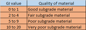
  • In  AASHTO soil classification system, Group index is also included along with soil groups and subgroups. Group index is a number used to refer the quality of soil used as subgrade material in highway. Its value generally ranges from 0 to 20. For two soils falling under same group and subgroup , the soil having lower GI value is better highway subgrade material in comparison to that of soil having lower GI value.


Step by Step Procedure for AASHTO soil classification system 

1. Distinguishing coarse grained / fine grained


First of all, find the percentage of soil passing US # 200 sieve (0.075 mm opening)

  • If % passing ≤  35%  ➡ coarse grained soil
  •  If % passing>35%  ➡ fine grained soil

2. Determination of  group and subgroups

  • For coarse grained soil, % of soil passing through US sieve # 10, #40 and #200 is also required in addition to liquid limit and plasticity index.

Now, after finding all of the mentioned values, compare the data from the AASHTO table of coarse grained. To compare go through the top to bottom until a line is found matching all of the properties calculated here.

  • For fine grained soil, only liquid limit and plasticity index is required.

 Now, just compare the data from the AASHTO table of fine grained. To compare go through the top to bottom until a line is found matching all of the properties calculated here.

3.  Determination of Group Index

  • For coarse grained

for A-1-a, A-1-b, A-3, A-2-4, A-2-5,   GI = 0

for A-2-6 and A-2-7, GI = 0.01 (F₂₀₀ -15) (PI -10)

  • For fine grained
GI = (F₂₀₀ - 35) [ 0.2+0.005(LL-40) ] + 0.01 (F₂₀₀ -15)(PI - 10)

if GI < 0 then take GI =0 and if GI >0 , the round off to nearest whole number.

4. Naming of soil

Finally as per AASHTO soil classification system, soil➡ soil group/subgroup followed by GI in parenthesis. e.g. A-7-5(10) , A-5(9).

AASHTO Table for coarse/fine grained soil 


AASHTO table for coarse grained


AASHTO table for fine grained

AASHTO soil classification example

Q. The result of sieve analysis of three soil is given next. It is required to classify these soils according to the AASHTO Classification system. Use the attached AASHTO Classification of Highway Subgrade Materials Table.


What is the classification of soil A,B and C?

sol:-
  • soil A
% passing # 200 sieve = 38 ➡ fine grained soil
plasticity index= (LL- PL) = 42-23 = 19

on comparing from AASHTO table for fine grained
soil group = either A-7-5 or A-7-6

as PI= 19 > (LL-30)  ⇒ soil group = A-7-6

Group Index, GI = (F₂₀₀ - 35) [ 0.2+0.005(LL-40) ] + 0.01 (F₂₀₀ -15)(PI - 10)

= (38-35) ( 0.2+0.005(42-40)) + 0.01 (38-15)(19-10)

= 2.7 ≈ 3 

so, soil A = A-7-6(3) 

  • soil B
% passing # 200 sieve = 33 ➡ coarse grained soil

% passing # 10 = 77 , #40 = 50 

and LL = 46 , PI= 46-29= 17

on comparing from AASHTO table for coarse grained

soil group = A-2-7

Group Index, GI = 0.01 (F₂₀₀ -15)(PI - 10)

 = 0.01 (33-15) (17-10) = 1.26 ≈ 1

 so, soil B = A-2-7(1)

  • soil C
% passing # 200 sieve = 63 ➡ fine grained soil
plasticity index= (LL- PL) = 47-24 = 23

on comparing from AASHTO table for fine grained
soil group = either A-7-5 or A-7-6

as PI= 23 > (LL-30)  ⇒ soil group = A-7-6

Group Index, GI = (F₂₀₀ - 35) [ 0.2+0.005(LL-40) ] + 0.01 (F₂₀₀ -15)(PI - 10)

= (63-35) ( 0.2+0.005(47-40)) + 0.01 (63-15)(23-10)

= 12.82 ≈ 13  

so, soil C = A-7-6(13)  


SUPERPOSITION METHOD/ METHOD OF TABLES OF FINDING DEFLECTION

  • Table method of finding deflection of beam is one of the best method of finding deflection of beam.
  • This method of finding deflection is very much beneficial in case of finding slope and deflection as per superposition method. 
  • As per superposition method , the effect of each and every load is considered separately and finally the effect of each loading is summed up.
  • This method is even very much helpful in case of analysis of indeterminate structure with the force method of analysis. By choosing the redundant , the effect of various loading is calculated at the desired position with the help of the table.
  • The table consists of slope and deflection equation of some standard type of beam under various standard loadings.

1. CANTILEVER BEAM WITH POINT LOAD

  • For 0 ≤ x  a 
Ө = (P/2EI) (X² - 2aX)

y = (P/6EI) (X³ - 3aX²)

  • For a ≤ x ≤ L

Ө = - Pa²/2EI

y = (Pa² / 6EI) (a - 3x)

2. CANTILEVER BEAM WITH CONCENTRATED COUPLE

  • For 0 ≤ x  a 

Ө = - Mx/EI

 y = - Mx²/ 2EI

  • For a ≤ x ≤ L
  • Ө = -Ma/EI

    y = (Ma/2EI) (a - 2x) 

    3. CANTILEVER BEAM WITH UDL

    • For 0 ≤ x ≤ a 

    Ө =(w/6EI)(3ax²-3a²x-x³)

    y = (w/24EI)(4ax³-6a²x²-x⁴)

    •  For a ≤ x ≤ L

    Ө = - wa³/6EI

    y = (wa³/24EI) (a - 4x)

    4. CANTILEVER BEAM WITH TRIANGULAR UVL

    • For 0 ≤ x ≤ a

    Ө = (w/24EIa)(x⁴-4ax³+6a²x²-4a³x)

    = (w/120EIa)(x⁵-5ax⁴+10a²x³-10a³x²)

    •  For a ≤ x ≤ L

    Ө = (- wa³/24EI)

    y = (wa³ /120EI)( -5x+a)

    5. SIMPLY SUPPORTED BEAM WITH POINT LOAD

    • For 0 ≤ x ≤ a

    Ө = (Pb/6EIL)(3x²+b²-L²)

    = (Pb/6EIL)(x³+b²x-L²x)


    •  For a ≤ x ≤ L

    Ө = (Pa/6EIL)(L²-a²-3(L-x)²)

    y = (Pa(L-x)/6EIL)(x²+a²-2Lx) 

    6. SIMPLY SUPPORTED WITH CONCENTRATED COUPLE

    • For 0 ≤ x ≤ a

    Ө = (M/6EIL)(-3x²+6aL-3a²-2L²)

    y = (M/6EIL)(-x³+6aLx-3a²x-2L²x) 


    7. SIMPLY SUPPORTED WITH UDL

    • For 0 ≤ x ≤ a

    Ө = (-w/24EIL)[4Lx³-6a(2L-a)x²+a²(2L-a)²]

    y = (-w/24EIL)[Lx⁴-2a(2L-a)x³+a²(2L-a)²x] 

    •  For a ≤ x ≤ L

    Ө = (-wa²/24EIL)(6x²-12Lx+a²+4L²)

    y = (-wa²/24EIL)(L-x)(-2x²+4Lx-a²) 

    8. SIMPLY SUPPORTED WITH TRIANGULAR UVL

    Ө = (-w/360EIL)(15x⁴-30L²x²+7L⁴)

    y = (-w/360EIL)(3x⁵-10L²x³+7L⁴x)


    Group index of soil

    Group index of soil is a number used to refer the quality of soil used as a subgrade material in highway construction.  Group index of soil ...